|
 |
How to use Tempurity™ to Collect Temperatures and other Data from a Home NetworkIntroduction
This primary purpose of this document is to describe how to configure your home network for use with the Tempurity™ System. Although examples of a method for home-based installation of temperature probes are given, in general, installation is covered elsewhere. The directions for network configuration differ depending on whether your Tempurity Server, the computer serving as the temperature collector, is inside your home network, or outside of it. In either case temperatures can be monitored from anywhere on the internet. You will be able to watch temperatures, define and send alarm notifications from any computer either inside or outside your home. For more detailed information see the Tempurity System User’s Guide, and the Tempurity Quickstart Guide which can be obtained from the download section of the Networked Robotics web page. The Tempurity System allows data collection and monitoring of more than just temperature. Almost any parameter can be monitored including contact (switch) monitoring, voltage monitoring, differential pressure any many other parameters. The Tempurity screenshot below shows the temperature of a swimming pool in the bay area of California where the sensor is mounted near the surface.
Installation
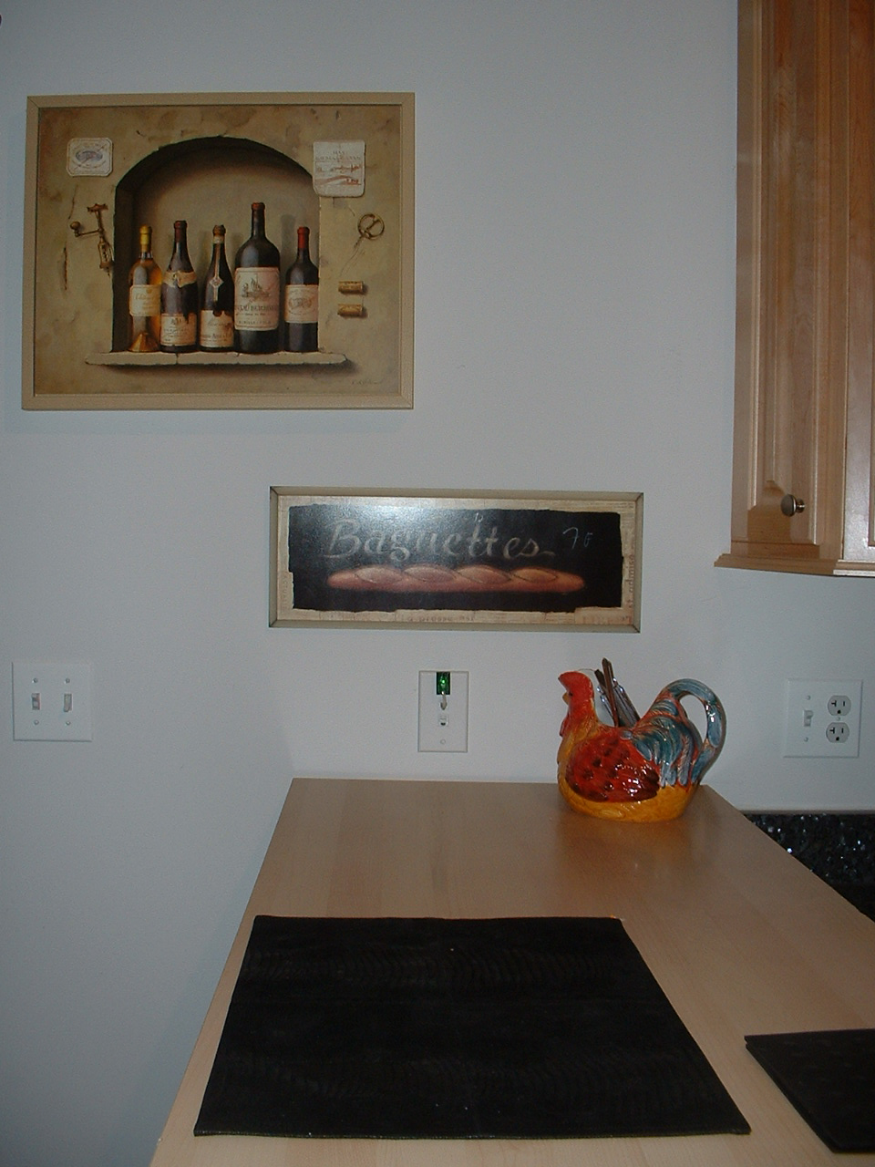
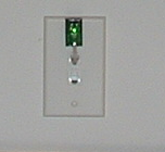
For detailed installation information see the Tempurity
System User's Guide. The photographs below show Networked Robotics TPL3
probes installed in a home in order to record room temperature. The digital
temperature probe is
plugged directly into a network wall plate. The green light indicates that
the probe is connected properly to Networked Robotics' NTMS4 network
hardware. This is an example of
the network-closet-based installation method described later in this
document and shows the location of some of the probes at the demo house.
Requirements
To collect temperatures you will need at least one Networked Robotics NTMS4 network device and at least one Networked Robotics digital temperature probe. To collect temperatures from multiple NTMS units you will need a home network router which are usually provided by internet service providers. The Networked Robotics NTMS4p can be used wirelessly. Configuring your Home Network for use with Tempurity
The Process of Configuring your Network for use with
Tempurity This document describes the process of configuring a
home network in cases where a Tempurity Server is outside your home network
and is collecting temperatures from Networked Robotics hardware inside your
home or where a Tempurity Server is inside your home and you wish to access
temperatures with an external Tempurity Monitor. In either case you will
need to: 1) Determine your router’s external address 2) Configure your router to allow external access to
either a Tempurity Monitor (if the Tempurity Server is inside the home
network) or to NTMS hardware (if the server is outside the network) 3) Follow the normal installation of Tempurity Server
and Monitor client software as defined in the Tempurity Quickstart Document The examples below are based on Linksys routers from
Cisco Systems. You may need to consult your user’s guide in order to find
the appropriate configuration screens for your brand of router. Home Router and Network Basics Most home routers have a single external network
address, called an IP address, and multiple internal addresses. All
connections initiating from outside the home network must be to the external
IP address. The Internet Service Provider (e.g. Comcast, Sprint, or AOL)
assigns you this address from a range of addresses allocated to their
organization. Usually the address is automatically assigned to the router
when you turn the router on. Network messages coming into the router from
the outside are usually discarded. Because the internet sees only one
external address, and there are many internal addresses, the router does not
know to which internal address/ computer the message should be sent. You
will need to tell the router that externally-originating messages destined
for Tempurity devices should be forwarded to the internal computer's
(Tempurity Server's) internal IP address or to the internal IP addresses of
Networked Robotics NTMS hardware on your network. In the router configuration you will identify the types
of external message that will be forwarded internally by
the external message's network (TCP) port address. For Tempurity this
will be either the network port address(s) you entered into your NTMS via
the NTMS Configuration Utility (when the Tempurity Server is external) , or
the fixed address 3010 which is the port used by external Tempurity Monitors
to talk to internal Tempurity Servers.
Determine your Router’s External Address Connect to your router according to the instructions in
the router user’s guide. Usually you will do this by entering the router's
default IP address, usually 192.168.x.1,
into a web browser. Enter
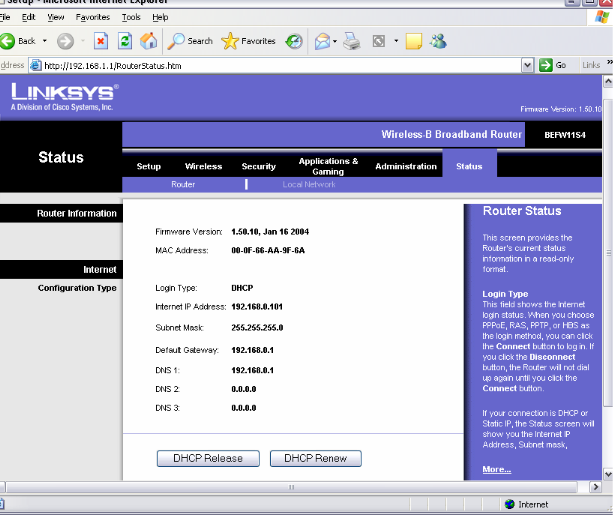
the router username and password as per the router's user's guide. On Linksys routers the “Status” screen is used to
determine the external IP address, shown below on the line “Internet IP
address”. This will be entered for every access to Tempurity from outside of
your home network. You should record this address.
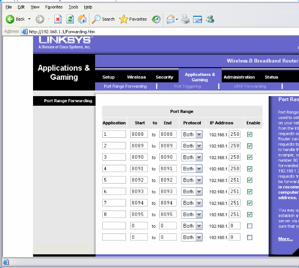
Configuring the Router for Access by Tempurity You will use the router’s port mapping procedures to
allow external access by Tempurity. On LinkSys routers this function is
enabled in a screen called Applications and Gaming (Multiplayer game servers
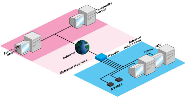
require the same procedures to allow connections by the outside). If the Tempurity Server is Outside the Home Network In the example below two NTMS4 network devices are
connected within the home network. Each of these are connected to four
Networked Robotics digital temperature probes that might be connected to a
room, refrigerator, or freezer anywhere in the house (not shown).
The figure below shows how port mapping allows the
Tempurity Server to connect through the router to collect temperatures. Note
that the port addresses must all be unique. These are assigned manually to
the NTMS via the Tempurity System's NTMS Configuration Wizard or NTMS
Configuration Utility.
In the Linksys screen above, “Application”, is a field
that can be any user-specified entry. “Port start and end” is the configured
NTMS network port for a given temperature port on the NTMS. “Ip address” is
the internal IP address that you gave to the NTMS device using the NTMS
Configuration Utility. Enable should always be checked. From within the Tempurity Server Configuration Utility
screen on a Tempurity Server outside the home network, each monitored device
will be identified using the router's external IP address and the unique
port address as follows: 192.168.0.101 8088 192.168.0.101 8089 192.168.0.101 8090
|